Background
From the beginning of the 3.1 (190 CID) liter engine project, I knew that I wanted to try out progressively wilder intake and exhaust setups while keeping most of the "lower end" of the engine the same. My preferred first step away from the stock Corvair intake is Weber IDA 3C carburetors. I am pairing the carbs with heads featuring larger exhaust tubes. Heads of this type are commonly known as "angle port" heads because the larger-diameter tubes must sit in the heads at angle to avoid interfering with the pushrods.
Plans changed though when I heard about the solid-lifter roller cam available through Ray Sedman of American Pi, Inc. Linn Richardson and I decided to build another engine from scratch, since we were going to have to pull the case apart anyway for the new cam. I partially funded the project by selling the Stage 1 engine to Linn's brother Dean.
Another customer of Linn's (John Rogers, of Franklin, NJ) wanted basically the same engine as me. I was happy to let Linn build John's engine first—he could be the guinea pig this time around!
Solid lifter roller cam component photos
The photos below are for the solid lifter roller cam components for John Roger's engine. His cam is a little milder than John Barnes' cam because he is running stock-sized exhaust tubes, exhaust manifolds, and mufflers.
|
A solid lifter roller cam is definitely a different beast, as these next few photos show. The valvetrain noise in a running car is much louder than stock, due to the basically solid lifters employed. |
|
Here is a close-up of one of the solid roller lifters. The early production two piece lifter sleeves were changed to a one piece design and all previous sleeves were replaced with the new design. |
|
It's hard to get a great comparison photo of stock and solid lifter roller cam profiles but this was the best I could do. A typical late model (-304?) cam is shown on the left and John Rogers' roller cam is shown on the right. The ramps are much less gradual with the roller cam—the valve opens very quickly and closes very quickly. One sign of this is the forcefulness of each exhaust "puff" as felt at the muffler while idling—a roller cam engine really packs a lot of force! |
|
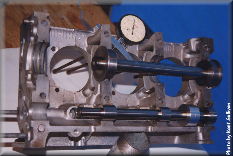
This photo shows a couple of the special tools that John Barnes made to ensure proper fit of the roller cam into the block. (The first one we received was ground wrong and it took awhile to locate the problem, so John spent some time make tools for the next round.) |


Solid lifter roller cam observations
Although the cam and carburetion for John Rogers' engine are quite a bit more radical than my Stage 1 approach, the result is still very streetable. During normal driving, the "man on the street" would only notice the increased valve train noise with John's engine. (It is running totally stock exhaust, right down to original-type 140 HP dual mufflers.)
During the time John Roger's engine was in my coupe for break-in, I was able to get a good feel for the "personality" of the roller valve train. When I cracked the throttle open more than about 1/3 of the way, things changed in a big way. Although the engine is exhaust-restricted, it clearly breathes much better than the Stage 1 engine and takes pretty good advantage of the increased venturi in the carburetors. As Steve Wren (FastVair mailing list owner) said, after taking my car for a spin in the summer of 1999:
"This car has got a huge bag of torque in the hiney-end, and surely some HP if we pushed the rev-counter higher. It felt very happy at 2500 RPM. We shifted short at 4500 since it is just breaking in. Really throws the car forward."
From solid to hydraulic
I'm glad I let Linn build John Rogers' engine first, because in the meantime, Ray started development work on a hydraulic lifter roller cam (HLRC). Ray offered to let me beta test the hydraulic lifter roller cam setup and I jumped at the chance! At about the same time, Linn hurt his back and became unavailable to work on the Stage 2 engine so John Barnes (the machinist for Stage 1) stepped in to also do the assembly. I also sold my solid-lifter roller cam setup to John. He's going to use it to help create a killer engine for his autocross car.
Hydraulic lifter roller cam component photos and specs
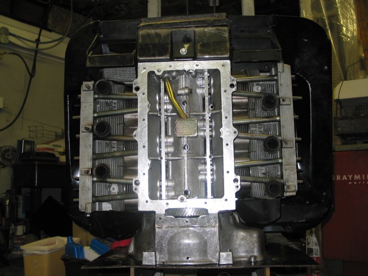
I will publish photos of the components once they are out of beta test phase and are commercially available. For now, the following picture shows the nifty one-off retainer system that John Barnes developed. This retainer system was developed to allow different lifter designs to be easily changed and installed for testing. The production system will not require extensive machine work on the case and will simply install with only a hand drill.
The cam we chose for the Stage 2 engine is pretty mild. You can check out the specs if you're curious. The bottom line is that the roller technology provides a lot of power without a radical cam grind.
Engine assembly & testing (hydraulic roller cam)
After many months of preparation by Ray and John, engine assembly started in August, 2001. Our goal was to get the car on the road in time for Western Canada CORSA's Corvairitis Treatment Day 2001 on September 29, 2001. Click here to read more about that odyssey.
Shortly after returning from Canada, the crank gear slipped (due to a weak key that we previously had not noticed) and the engine stopped dead. With the engine apart to fix that problem, Ray decided to investigate why the valve train was so noisy. His investigation eventually led to the conclusion that the original approach to the lifter design was flawed. Ray then spent quite a bit of time over the next two years developing a superior solution.
The good news is that Ray solved the problem in late 2003! Ray flew back to Seattle and installed this incarnation of the HLRC system in my engine at the end of January, 2004. The engine is currently restricted on the intake side with 27 mm chokes (venturis) and is electronically rev limited by the SafeGuard to a maximum engine speed of 5,800 RPM. The exhaust has stock exhaust tubes in the heads and stock exhaust logs flowing into a custom single muffler system (two 2" inlets and one 2.5" outlet). These intentional restrictions are placed on the engine to help ensure the reduction of overzealous running of the engine during the testing phase. I plan to have several different people in my area drive the car to gather impressions and different driving patterns.
Initial tuning and testing was done on a chassis dyno at the Carburetor and Fuel Injection Connection in Kirkland, WA. A total of eight pulls were completed on their Dynojet inertial load chassis dyno. Final tuning of the air/fuel mixture and ignition settings were done on the dyno. After these settings were determined, back-to-back pulls showed a repeatability of about 1 ft/lb of torque between the runs. The engine showed a very flat torque curve from 2,000 to 4,000 RPM and gently fell off from there to the set 5,500 RPM limit for these tests. Road torque averaged about 168 ft/lbs. between 2,000 to 4,000 RPM.
At this stage of the project, Ray and I are focusing on the operational aspects of the HLRC system. We are specifically not looking at horsepower numbers but are instead looking for a broad torque curve. The above results are consistent with our goals at this stage in the project.
Ray and I took the engine on a shake-down road trip of about 400 miles (to Portland, OR and back). No problems were encountered and the engine ran very smoothly and quietly at average road speeds of 3,500 RPM.
What's next?
The first order of business is to get a lot of miles on the engine—a few thousand at least. Assuming that continued testing goes well, the larger chokes (venturis) will be installed this summer—probably 34 mm—and we will re-dyno the engine to tune it and measure torque and horsepower. I may also install a different exhaust system, depending on what the dyno tells us about restrictions in the system. Once that is sorted out, I will post driving impressions here. Suffice to say for now that the engine runs great and is a joy to drive!
Note: After a few years of hard work, testing and development our efforts have paid off. The HLRC system is performing within design expectations. Ray is currently working on the production aspects of the HLRC system so these kits can be made available to any Corvair engine builder. If you would like to be put on the notify list for this HLRC system, visit American-Pi's web site and send a note to Ray.